Detecting surface defects with fringe projection
Article

Authors: Sean Lau, Kai Loh and Waiel Elmadih
The need
Advances in manufacturing technologies have significantly increased the throughput of products across various sectors, enabling industries to meet the growing demands of the global market. This increase in production capabilities necessitates an evolution in quality assurance methodologies to ensure that the increasing volumes of output do not compromise product quality.
Traditionally, metrology—the science of measurement—has relied on sampling single parts from a batch for examination in controlled environments, such as clean rooms. While effective for smaller-scale production, this method falls short in today’s high-output manufacturing landscape. It is increasingly apparent that there is a critical need for a new measurement technology.
This technology must not only accommodate the pace of modern manufacturing but also provide a more comprehensive understanding of each part produced, enabling the measurement of a much higher number of parts to maintain stringent quality standards. Enter fringe projection, a cutting-edge metrology solution perfectly suited to meet these demands.

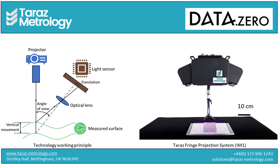
Figure 1. Fringe projection working principle (left) and the Taraz Fringe Projection System (right)
Fringe projection? What is that?
Fringe projection is a technique used in three-dimensional (3D) measurement and imaging of forms and surfaces. It involves using high-quality projector to project series of predetermined light patterns onto a surface. The deformation of said patterns caused by the surface’s contours are then captured via a set of calibrated cameras. Smart algorithms are then employed to analyse the deviations of the captured patterns from the original projected patterns and then creating a 3D model of the part. Taraz Fringe Projection System (IM1) has the advantages of high accuracy and fast data acquisition, making it well suited for industrial 3D measurements.

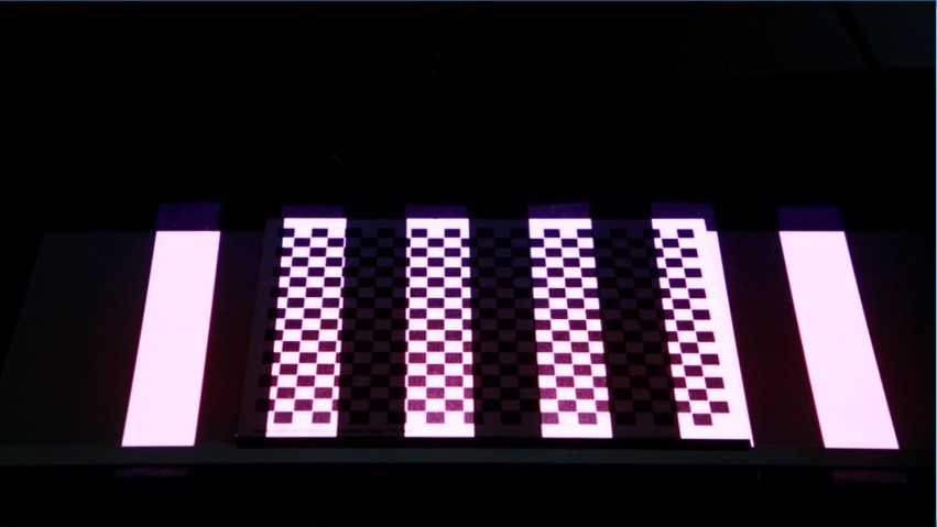
Figure 2. Fringe projection patterns projected on to a calibration artefact.
The application
Fringe projection can be used in various applications including automobile, coatings and extrusion monitoring. In DAT4Zero project, our fringe projection technology has been further developed to aid with quality control of metallic parts with drilled holes; specifically, determining the size and location of drilled holes in automobile aluminium parts.
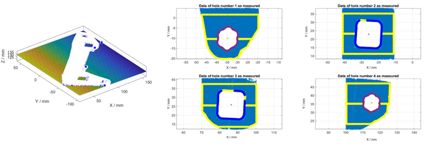
This process is remarkably streamlined, amounting to a “push-button” solution that offers rapid and accurate measurements in under five seconds. Following the acquisition of the point cloud, a sophisticated feature analyses algorithm comes into play. This smart algorithm has been specifically developed to identify the holes and their exact locations on the aluminium part. By analysing the point cloud data, the algorithm can differentiate between the intended features and any anomalies or variations in the surface, focusing on the critical attributes of each drilled hole.
Once the holes and their characteristics have been accurately identified, the system then proceeds to compare this real-world data against the original design. This comparison is crucial, as it determines whether the physical part meets the design specifications to a high degree of precision. The system assesses whether each hole’s size and location fall within the acceptable tolerances set forth in the design parameters.

Figure 3 The smart feature analyses algorithm in action: surface fitted to measured part data (left), and determining the size and location of drilled holes (right)
A vital aspect of this process is its proactive approach to quality control. By rapidly and automatically measuring a large number of parts with fringe projection, manufacturers can detect and address potential deviations in the manufacturing process before they exceed tolerance limits. This early detection mechanism allows for timely adjustments to be made, significantly reducing the likelihood of rework and scrap.
